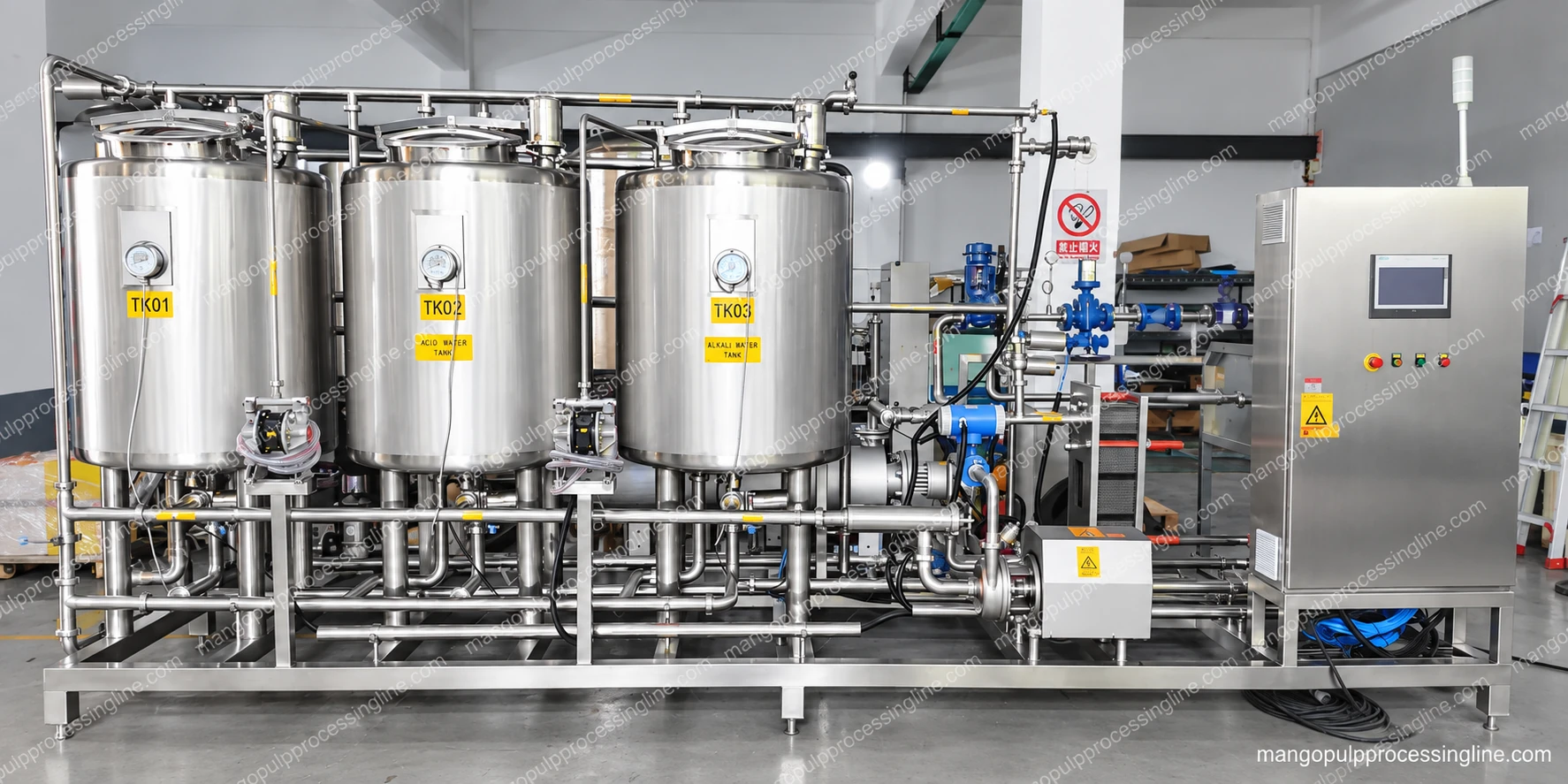
Give the next machine a controlled supply
A buffer vessel receives pulp from the upstream process and provides an intermediate supply to the next stage. The working volume is selected around the difference between those flows and the operating sequence, rather than using the gross vessel volume as usable storage.
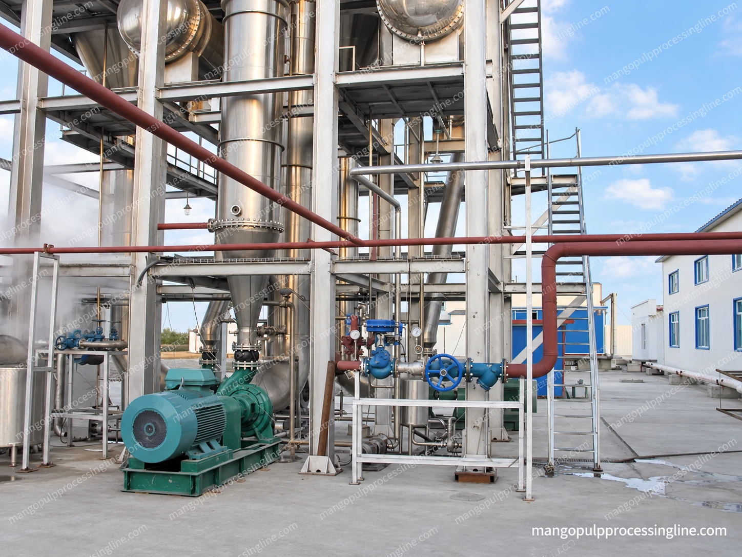
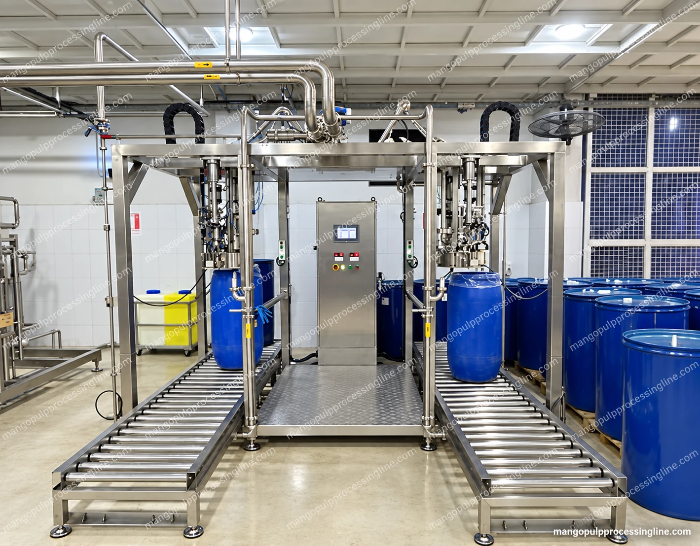
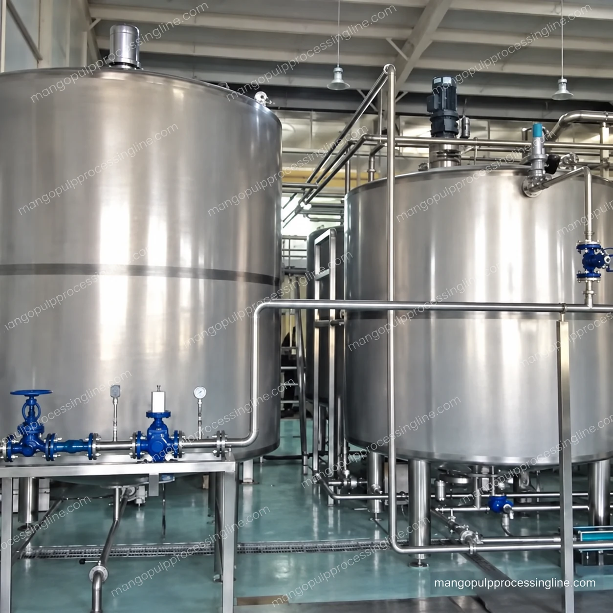
The pictured connected tanks show top fittings, lower outlets and surrounding pipework. They illustrate a process-vessel arrangement; the volume, agitation and instrumentation are specified for the selected mango duty.
Select the pump for the pulp at its operating temperature
Pulp viscosity, fibre, temperature and the pressure required by the downstream equipment all influence product transfer. The pump selection also considers the vessel outlet, available inlet conditions and the pipe route to the thermal machine or evaporator.
The transfer pump is specified as part of this assembly. A particular pump technology, model or duty is not implied by the vessel photograph. The thermal skid can include its own product-feed pump, so the transfer arrangement must avoid assigning incompatible flow duties to two connected machines.
| Design input | Why it matters |
|---|---|
| Pulp condition | Viscosity, fibre and temperature affect product handling |
| Working volume | Usable buffer must suit the operating sequence |
| Downstream duty | Required flow and pressure follow the connected process |
| Outlet and pipe route | Connections, elevation and losses affect pump selection |
| Cleaning path | Vessel, pump and transfer lines must be included in the intended cleaning circuit |
The balance vessel at the thermal inlet
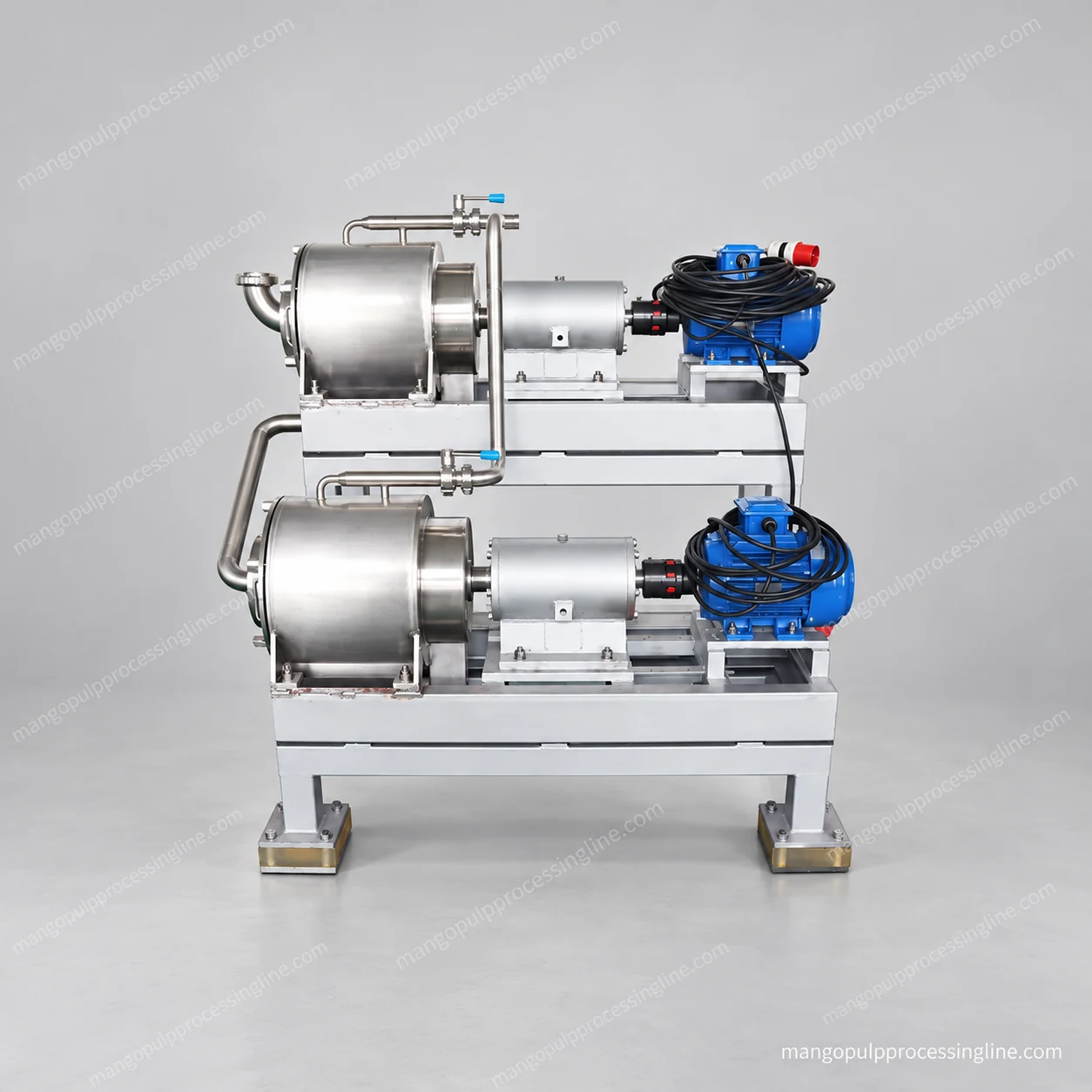
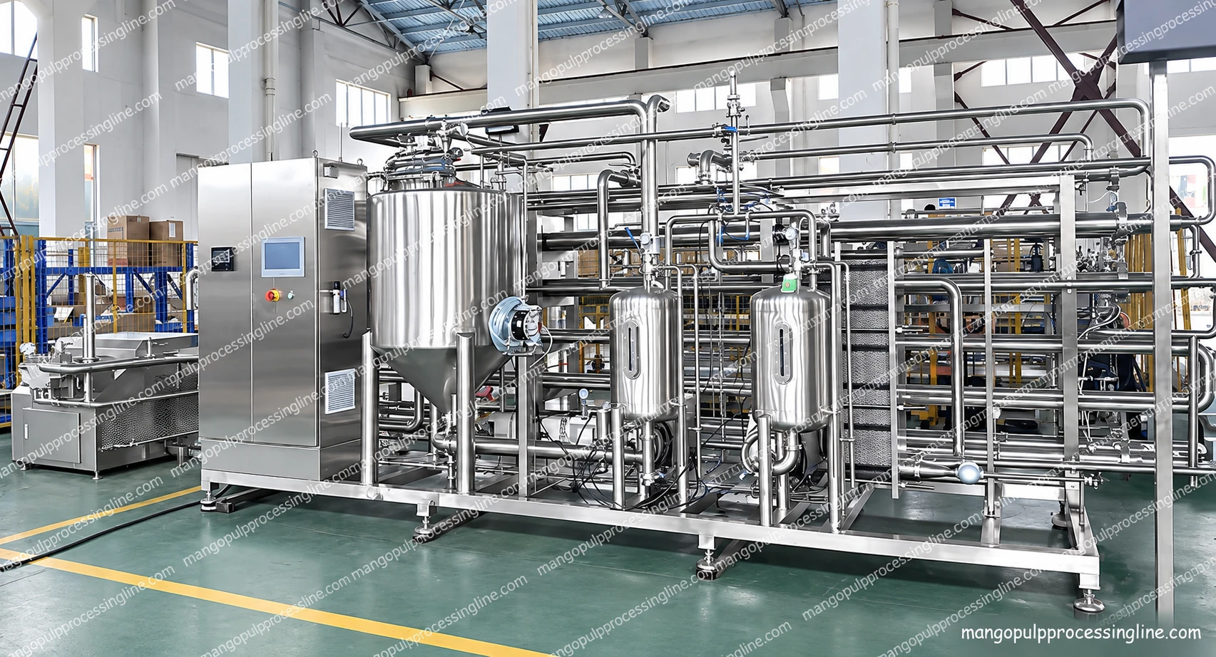
The tube-in-tube product scope includes a balance tank and a product pump. The pictured thermal skid shows how those items sit alongside the heat-transfer and utility sections. They form the immediate feed interface of the thermal process rather than replacing all upstream storage.
Plan emptying and cleaning with the product route
Vessel outlet position, the pump connection and low points in the pipe route affect how product is recovered and the circuit is drained. Access to seals, valves and any fitted agitator is considered in the layout.
Closed tanks and transfer piping can be included in a configured CIP circuit. The final circuit definition identifies the surfaces reached, return route and cleaning duty; a tank connected by a pipe is not automatically covered by every cleaning cycle.
Common questions
Can this assembly be added to an existing pulp front end?
It can be considered as an integration package. The incoming pulp flow, current vessel arrangement and receiving machine’s feed requirement define the useful vessel and pump scope.